 |
|
|
|
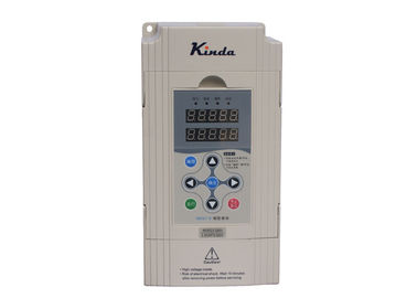
Residential Vfd Pump Drive , Water Supply Pump Inverter Drive Energy Saving
Product Details:
Payment & Shipping Terms:
|
| Control: | Main/slave Control Energy Saving | Installation: | Simple Wiring Installation |
|---|---|---|---|
| PCB Protection: | Spray Three Anti-paint To Protect The Circuit Board Intelligently And Efficiently | Design: | Modular Design, Compact Structure, Easy Maintenance And Enhanced Product Interchangeability |
| Start Up: | Simple Parameter Setting, One-button Start Automatic Addition And Subtraction Pump Control | Run: | Smooth Main/slave Switching, No Change In Water Pressure |
| High Light: | pump frequency converter,vfd pump control |
||
Residential Area Variable Frequency Drive Pump Control Water supply
When the water supply automatic control system is working, when the water consumption is changed by the high sensitivity pressure sensor installed on the water supply pipe network, the device detects the pressure change of the water supply pipe network. When the pressure of the pressure transmitter is the largest, the frequency of the inverter is the lowest, the minimum speed of the pump motor. When the pressure of the pressure transmitter is the smallest, the frequency of the inverter is the highest, the speed of the pump motor is the highest, and the frequency of the inverter changes with the water consumption. And change.
After the microcomputer judges the calculation and compares it to the set pressure, it sends a command to change the frequency to the controller. By changing the frequency, the controller automatically adjusts the peak and valley water consumption to ensure that the water supply network pressure is constant, changing the speed of the pump motor and the number of pumps activated.
Constant pressure water supply inverters are widely used in residential, hotel, agricultural constant water pressure stabilization products.
![]()
| Function code | Default value | Set value | Description | |
| F1-11 | 1 | I# inverter | 1 | 1# inverter (master), it must connect the pressure sensor. |
| 2# inverter | 2 | 2# inverter (slave / standby master), connect the pressure senor. | ||
| 3# inverter | 3 | 3# and 4# inverters (slave). | ||
| 4# inverter | 4 | Warning: the address of each inverter cannot be the same, otherwise, the system will work abnormally. | ||
| F0-00 | 1 | 2 | Multiple pumps system | |
| F0-01 | 0.4MPa | Customer set | 1. Please set it correctly based on requested pressure, the unit is MPa, 1MPa=10bar. | |
| 2. Most of the family used systems, the pressure is 0.3~0.4MPa (3~4bar) | ||||
| F0-02 | 80% | Customer set | Wake up pressure; it is the percentage of F0-01. | |
| F0-03 | 0 | 0 | It must be set as “0” while use 0~10V remote pressure gauge. | |
| 1 | It must be set as “1” while use 4~20mA pressure transducer. | |||
| F0-04 | 1.6MPa | 1.6MPa | 1. To set the maximum measure range of pressure transducer. | |
| 2. It must be set correctly, otherwise it may cause pressure is inaccurate. | ||||
| F0-25 | 300Min | Customer set | To set the running time as master pump, when time arrive, it switches to next pump as master. | |
| When set F0-25=0, this pump will only work as slave pump. | ||||
![]()
Contact Person: Tim
Tel: +8618665335699
-
Single Machine Variable Frequency Drive Pump Control Intelligent Water Supply
-
Water Supply Variable Frequency Drive Pump Control Constant Pressure 0.4kw - 450kw
-
Multi Machine Variable Frequency Drive Pump Control Water Supply Energy Saving
-
Intelligent Constant Voltage Vfd Pump Control , Pump Frequency Converter
-
Automatic 1.5KW Variable Frequency Drive Pump Control Compact Structure
-
Intelligent Water Supply Variable Frequency Drive Pump Control 15KW 380V - 460V


